Development of Polygonal Toroidal Micro Optical Resonators
Research
Development of Polygonal Toroidal Micro Optical Resonators
Light in and out of containers that confine light.
Tanabe Lab. has realized a polygonal silicatroid micro optical resonator that strongly confines light. The structure was fabricated by a combination of isotropic etching, anisotropic etching, and laser reflow, and is now in the process of measurement.
Conventional silicatroid resonators have very high performance, but their circular shape makes it difficult to control the coupling efficiency with tapered fibers. The newly developed octagonal silicatroid resonator allows longer coupling lengths, which results in stable coupling efficiency, and its smooth corners maintain high performance. Stable coupling is an important factor for practical applications such as optical frequency comb and particle detection using silicatroid resonators.
In this study, (1) anisotropic etchant KOH (potassium hydroxide) was used as a silicon sacrificial layer etchant, and the structure was fabricated by combining it with isotropic etching (Figure 1). Furthermore, it was found that the bonding efficiency can be controlled by using the edge and corner portions separately (Figure 2).
Part of this research was sponsored by the Strategic Information and Communications R&D Promotion Program (SCOPE). This research was also supported by Toray Science and Technology Research Grant and Keio University Next Generation Research Project Promotion Program.
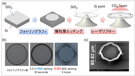
(a) Fabrication process of a conventional silicatroid micro optical resonator (b) Optical micrograph of the process up to the formation of the octagonal silicon post (top view). The silicon post is visible because the glass is transparent. (c) Octagonal silicatroid micro optical resonator with waveguide formed by laser reflow.
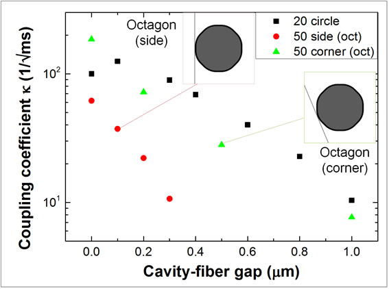
The red points are when the edge of the resonator is used for coupling, and the green points are when the corner of the resonator is used for coupling. Despite being the same resonator, the coupling coefficients are very different. By using this method, the coupling efficiency can be controlled by the contact points, which was previously possible only by adjusting the gap in nanometers.
- Categories
- 研究トピックス